

1. POINTS AND CROSSINGS are track components which facilitate diversion of railway vehicles from one line to another. On INDIAN RAILWAYS there are approx. 1, 10,000 points & crossings.
2. POINT is a pair of tongue rail and stock rail along with necessary fittings.
3. CROSSING is a device introduced in the track to permit movement of wheel flange at the intersection of two running lines. It has certain gaps over which the wheel treads jumps.
4. The arrangement of Points & Crossings for diversion of traffic from one route to another is called a TURNOUT. Turnouts are required to divert the railway vehicles from one track to another track with lead rails these tracks may be either parallel or diverging or converging. On Indian Railways more than 63400 route kilometer of track includes about 110000 points and crossings.
TURN-OUT LAYOUT


Parts of Turnout :
a. SWITCH PORTION (SRJ to HOS)
b. LEAD PORTION (HOS to TNC)
c. CROSSING PORTION(TNC to HOC)
Over all length of Turn out:- The overall length of turn out is measured along the
straight from SRJ to HOC some times this is followed by Turn-in-curve.
1. Turnouts are called left Hand or Right Hand depending on the side on to which
the rolling stock gets diverted
2. The tip of tongue rail is called Actual Toe of Switch
3. The joint between Stock Rail and approach rail is called Stock Rail Joint
1. SRJ - Stock rail joint
2. TTS - Theoretical toe of switch
3. JOH - Junction of heads
4. HOS - Heel of switch
5. TOC - Toe of crossing
6. TNC - Theoretical nose of crossing
7. ANC - Actual nose of crossing
8. HOC - Heel of crossing
Stock Rail:- A running rail against which a tapered and moveable tongue rail rest in fully closed position.
Tongue Rail: - A tapered and moveable rail machined from ATS to JOH the head thickness is minimum at ATS and gradually increasing to head width of tongue rail at OH.
Switch
A pair of tongue rails with necessary connects and fittings is called switch.
Right Hand Switch

FACING DIRECTION AND TRAILING DIRECTION
According to direction of movement of vehicle, when movement is from points to crossings it is called “Facing Points” and from crossing to point it is called “Trailing Point”
TYPES OF SWITCHES
Ordinary switches in which the foot of stock rail is placed in order to accommodate the tongue rail.
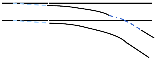
• STRAIGHT SWITCHES: In straight switches the tongue between ATS and HOS is straight. Therefore no versine is obtained in straight switches. Straight switches are having greater switch angle as compared to curved switch.
Therefore more lateral thrust at ATS is experienced by vehicle .
The tongue rails of these switches are straight
– Advantage: same tongue rail can be used for RH and LH turnout
– Disadvantage : Lurch due to abrupt change of direction
• CURVED SWITCHES: In curved switch the curvature starts from ATS and the versine during pre-curving of tongue rail and stock rail is necessary and the designed versine is obtained. In curved switches the switch entry angle is small therefore less lateral thrust is experienced by vehicle at ATS. Hence curved switches provide smooth entry.
The tongue rails of these switches are curved to provide smooth entry into the
turnout.
– Advantage: Discomfort to the travelling public is reduced. Wear is reduced.
– Disadvantage: Because of single pull arrangement on IR, the clearance between tongue rail and stock is inadequate at some locations.
Historical Development of Switches
1. Stub switches
2. Modified stub switches
3. Split switches
4. Undercut switches
5. Overriding switches
6. Thick web switches
1. STUB SWITCHES:- In earlier days short pieces of rails which could be
connected to either of routes by physical shifting were named as “Stub
switch”. Three rail pieces one each for tongue rail and crossing were used.

2. MODIFIED STUB SWITCH
The third rail piece was replaced by a built up crossing then it is called “Modified Stub switches”. These arrangements were structurally weak and cumbersome and difficulties due to thermal movement of rail were experienced. Above problems were over come by evolution of the split switches


3. SPLIT SWITCH

4. UNDERCUT SWITCH

5. OVERRIDING SWITCH
In which only the foot of the tongue rail is planed so that it overrides the foot of the stock rail which is maintained full section. Only overriding switches have been standardised on Indian Railways.


Advantages
• The stock rail being un-cut is very strong.
• All the work of manufacture will be confined to the tongue rail therefore it is economical.
• The tongue rail is supported by the stock rail in set condition of points hence the load is distributed partially to stock rail and partially to tongue rail.
Components of Point & Crossing
1. TONGUE RAIL 2.STOCK RAIL. 3. SWITCH. 4.POINTS
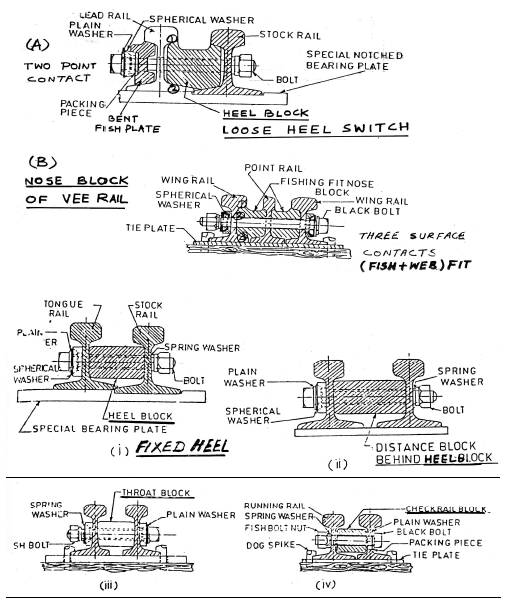
• HEEL OF SWITCH : Imaginary point on the gauge line between the end of tongue rail & lead rail in case of loose heel switch Point on the gauge line opposite the centre of heel block in case of fixed heel switch.
LOOSE HEEL SWITCHES :The tongue rail is fastened to the stock rail at the end and during operation of point the whole tongue rail from toe to heel moves to enable the movement of free end of tongue rail. The fish plate is slightly bent. The tongue rail is fastened to stock rail with fishing fit blocks and 4 bolts. 2 bolts in lead rail are tightened while 2 bolts in tongue rail are snug fit (hand tight) to allow movement of the tongue rail. Due to impact of wheels on joints fish holes are elongated and tongue rail starts creeping

FIXED HEEL SWITCHES
The tongue rail design doesn’t end at the heel of switch but extends further in lead portion. Throw of switch is achieved by flexing of tongue rail such as elastic
deformation on tongue rail. 6400mm minimum length is necessary to afford required throw.


Switch length & Tongue rail length
• The distance between the actual toe of switch to heel of switch is called switch
length.
• For loose heel switch – Tongue rail length = Switch length.
• For fixed heel switch - Tongue rail length > Switch length
• HEEL OF SWITCH
This is a imaginary point at the centre of heel block.
This is a imaginary point at the centre of heel block.
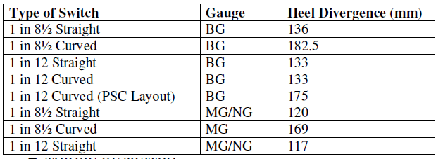
• HEEL DIVERGENCE
– The distance between the gauge face of stock rail & tongue rail at the heel of switch is called heel divergence.
– Measured at right angle to the gauge face of stock rail .it is fixed to avoid the grazing of non gauge face side of tongue rail at the heel by the wheel flanges.
– Clear distance between the heads of tongue rail & stock rail is called heel clearance.

THROW OF SWITCH
– The distance through which the toe of tongue rail moves when points are operated.
– Measured between the gauge face of stock rail & non –gauge face of tongue rail at the toe of switch.
Min.95 mm. rec.115 mm. (FOR BG)
Min. 89 mm/rec 100 mm. (FOR MG)
For new works on B.G
Min. 115 mm may be increased upto 160 mm

– It is the angle contained between the gauge line of tongue and stock rail in closed position of tongue rail(for straight switch)


Theoretical Toe of Switch
It is the point of intersection of the gauge lines of a tongue rail at its point and its
stock rail in closed position.
JUNCTION OF HEAD
JOH is the point at tongue rail where tongue rail attains full cross section. The minimum clearance at JOH between tongue rail and stock rail. Is kept 38 mm. The housing should be done upto JOH. The locations of JOH from ATS for Various types of switch are
• 6400mm c/s on PSC sleeper 52kg rail 3023mm
• 6400mm c/s on PSC sleeper 60kg rail 3229mm
• 10125mm c/s on PSC sleeper 52kg rail 5540mm
• 10125mm c/s on PSC sleeper 60kg rail 5836mm
• 4725mm straight switch on wooden sleeper 2215mm
Clearance at JOH
Throw of switch is decided from the consideration of minimum clearance obtained between the stock rails and tongue rail at JOH.
SWITCH ASSEMBLY
The rolling stock negotiating the turnout impinges first on the switch assembly. Therefore toe of tongue rail experiences high impact forces and the lateral forces
resulting in the wear of tongue rail and deterioration of turnout geometry.
Components of Switch
1. Stretcher bars 2.Gauge tie plate 3.Heel block
4 Distance block 5.Slide chairs 6. Spherical washers
7.Stretcher Bar 8. Switch stop and slide blocks
Stretcher bars
Stretcher bars are made of spring steel flats of size 75mm x 12mm for B.G. and 65mm x 10mm for M.G. These are fitted to tongue rails by means of M.S. brackets in vertical position. Turned bolts are used for connections. Cleats (lugs) are used to connect the stretcher bars with pull rod with the help of turned bolts. First stretcher bar is called “Leading stretcher bar” and subsequently “First following” and Second Following stretcher bars”.
Holes drilled for turned bolts should be of exact diameter to eliminate any play. The leading stretcher bar is provided below the stock rail foot with 1.5mm clearance to prevent the toe from lifting when tongue rail is loaded at or near the heel. Diameter of turned bolts and holes are 20mm for B.G. and 18mm for M.G.
To operate both the tongue rail simultaneously using one lever
Min. no. _ FOR 1 IN 12 & 1 IN 8.5 2
– FOR 1 IN 12 PSC LAYOUT 4
– FOR 1 IN 8.5 PSC LAYOUT 3
– FOR 1 IN 16 & 1IN 20 3


Gauge Tie Plate
To maintain the correct gauge the gauge tie plates are provided under the toe of
switch and nose of crossing. Sizes of gauge tie plates are –
B.G. 250 x 12 mm M.G. 220 x 10 mm
Distance Block
To connect to different rail at desired distance and \or inclined
– Fishing fit block (act as fish plate also)
• Heel block of loose heel switch
• Nose block of vee piece of crossing
– Web fit block
• Heel block of fixed heel switch
• Distance block behind heel of switch
• Throat block of crossing
• Check block between running rail and check rail

Slide Chairs

- To facilitate smooth movement of tongue rail
- In OR Switches slide chairs are raised by 6 mm to provide support to the flange of tongue rail
- Stud bolts(Thick headed and Thin headed) used for fixing the first few slide
- chairs are thin headed bolts so as to permit housing of tongue rail

Switch Anchor
Switch anchors are optional fittings to be used behind the heel of switch when excessive relative longitudinal movement between the tongue rail and stock rail occurs it prevents or minimize the relative movement of tongue rail with stock rail.
Switch Stops
Between toe and heel, tongue rail is not held to the sleeper(no lateral strength) To provide lateral strength switch stops in form of U shaped bend plate are bolted to the web of tongue rail to bear against web of stock rail in closed position-
In 1 in 12 & 1 in 8.5 Cu. 2 Nos.
In 1 in 12 & 1 in 8.5 Cu. 2 Nos.
In 1 in 8.5 Straight. 1 Nos.

Slide Blocks
• In curved switches (other than 1 in 8.5curved switches)slide blocks are provided to increase lateral support to tongue rail
• These are bolted to stock rail against which tongue rail will bear in closed position

Spherical Washers:- Spherical washers has been designed consisting of two pieces in spherical contact which will adjust themselves to allow for any deviation of the bolt in either horizontal or vertical direction and has the effect of centralising the load on the bolt for any angle. It is used to obtain flush fit of the head of the nut of the bolt with the web of the rail in switch and crossing assembly. It is necessarily used where shank of the bolt is not at right angle to the axis of the rail. These washers are used on skew side. In IRS turnout with straight switches these should be provided on the left hand side invariably in the switch assembly.
• Used to obtain flush fit of the head or the nut of bolt with the web to rail
• Required if axis of bolt is not at right angle to the surface against which bolt will rest.


LEAD
Track portion between HOS to TNC is called lead of a turn out. It is measured along the straight.
Curved lead = switch length + lead length
CROSSING
A crossing is a device introduced at the junction where 2 rails cross to permit the
wheel flange of a railway vehicle to pass from one track to another track.
Theoretical Nose of Crossing
It is the theoretical point of intersection of the gauge lines of a V of crossing which is used as a reference point for all calculations. It is an imaginary point.
Actual Nose of Crossing
It is the point at which the spread between the gauge lines of a crossing is equal to web thickness of rail section from consideration of manufacture and strength.
Throat of crossing
It is the point at which the converging wings of a crossing are closest to each other.
Toe of crossing
Starting point of front leg of crossing is called Toe of Crossing. (Generally wing rail in acute crossing.)
Heel of Crossing
End of back leg of crossing is named as heel of crossing. Inclined distance between toe of crossing and heel of crossing is known as length of crossing.
Angle of Crossing
Angle contained between the gauge lines of V pieces measured at TNC is known as angle of crossing.

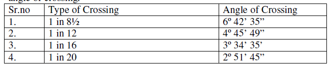
Number of Crossing
The co-tangent of the angle of crossing is designated as number of crossing.
i.e, 1 in N where N may have value of 8.5,12,16,20 etc.
Method of assigning the number of crossing:-
1. Right Angle Method This method is used in IR N = cot F
2. Centre Line Method N = ½ cot F/2
3. Isosceles Method N = ½ cosec F/2
Acute Crossing, Obtuse Crossing and Square Crossing:-
In a turnout only one rail of one track crosses one rail of other track. The angle between gauge lines of intersecting rails is named as “Acute Crossing” if this angle of intersection is less than 90º (i.e Right Angle). It is named as “Obtuse Crossing” is the angle of intersection is more than 90º. The crossing is called “Square Crossing” when angle of intersection is right angle.
Types of Crossing
(1) Built up crossing
(2) CMS crossing
(2) CMS crossing
(3) Swing nose crossing
(4) Spring crossing
(4) Spring crossing
A. Built up Crossing

Check Rail and Check Rail Clearance
Check rails are provided opposite the nose of crossings to guide and check even the worst worn wheel after the entry to avoid the possibilities of hitting the nose
of crossing and guidance in the appropriate gap in the facing direction.
Clearance is initially kept 44mm for B.G. and 41mm for M.G. It is allowed to increase due to wear on sides of the check rail and V piece upto 48mm for B.G. and 44mm For M.G. The check rail clearances are to be adjusted before reaching the maximum limit.
The end of both check rails and rear end of wing rails are flared to increase the clearance and ends from 44mm to 60mm in B.G. and 41mm to 57mm for M.G. In a distance of 610mm check rails may also be machined to get this clearance at the end.
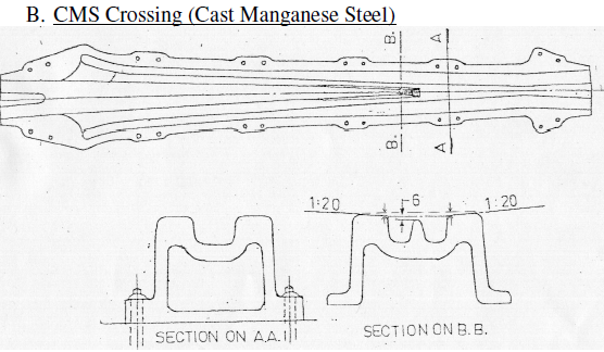

CMS crossing are cast as one body, hollow at the bottom with cros ribs, keeping
metal thickness enough to suit the load. These crossings give satisfactory service.
Earlier it was observe red that cracks developing in the crossing and wear was also more, but these deficiencies have been overcome to some extent. Its initial cost is more but maintenance cost is less. Therefore it is economical.
Spring or Moveable wing crossing:-
This is a type of built-up crossing in which one wing rail is movable and is held against the Vee of crossing with a strong spring. When vehicle passes over the main track no gap is to be negotiated by wheel. When vehicle coming from diverging track the moveable wing is forced out by the flange of wheel it self. The wheels are guided by the check rails attached to opposite running rail. Earlier these were used in slip siding and in emergency cross over due less traffic on turnout side. The life of this crossing is much more than ordinary built-up crossing.
Built up Crossing v/s CMS Crossing


TURN-IN-CURVE
The curved track porion between HOC to Fouling mark is called Turn-in-curve. Turn outs are designated facing towards tongue rails depending on the side to which the rolling stocks get diverted - LH Turn out or RH Turn out Similarly tongue rail, stock rail, wing rails as well as check rails are called LH and RH depending on their position looking in the facing direction of the points.
Speed over Turn-out Curves –
(1) The speed of trains over non-interlocked facing points shall not exceed 15 kilometres per hour in any circumstances and the speed over turnout and cross overs shall not exceed 15 kilometres per hour, unless otherwise prescribed by approved special instruction, which may permit a higher speed.
(2) Subject to provision of sub-rules (1) a train may run over interlocked facing points at such speed as may be permitted by the standard of interlocking. Turnouts on running lines with passenger traffic – Turn-outs in running lines over which passenger trains are received or despatched should be laid with crossing, not sharper than 1 in 12 for straight switch. However, 1 in 8-1/2 turn-out with curved switches may be laid in exceptional circumstances, where due to limitation of room, it is not possible to provide 1 in 12 turn-outs. Sharper crossings may also be used when the turn-out is taken off from outside of a curve, keeping the radius of lead curve within the following limits :–
Gauge & Minimum radius of lead curve


Where it is not practicable to achieve the radius of curvature of turn in curves as specified above on account of existing track centres for the turn-out taking off from curves, the turn in curves may be allowed upto a minimum radius of 220m for B.G. and 120m for M.G. subject to the following :–
(a) Such turn in curves should be provided either on PSC or steel trough sleepers
only, with sleeper spacing same as for the main line.
(b) Full ballast profile should be provided as for track for main line Emergency crossover between double or multiple lines which are laid only in the trailing direction may be laid with 1 in 8-1/2 crossings In the case of 1 in 8-1/2 turn-outs with straight switches laid on passenger running lines, the speed shall be restricted to 10 km.p.h. However, on 1 in 8-1/2 turn-outs on non passenger running lines, speed of 15 km.p.h. may be permitted.
(3) Speed over interlocked turn-outs –
(a)Speed in excess of 15 Kmph may be permitted for straights of interlocked turnouts only under approved special instructions in terms of GR 4.10/1976
(b) In the case of 1 in 8½, 1 in 12 and flatter turnouts provided with curved switches, higher speeds as permitted under approved special instructions may be allowed on the turnout side, provided the turn-in curve is of a standard suitable for such higher speeds. While permitting speed beyond 15 Kmph provision below may be kept in view.
The permissible speed on turnouts taking off on the inside of the curve should be
determined by taking into consideration the resultant radius of lead curve which
will be sharper than the lead curve for turn outs taking off from the straight. 1 in
8½ turn outs should not be laid on inside of curves.
(c) the permissible speed on turn-outs taking off on the inside of the curve should be determined by taking into consideration the resultant radius of lead curve which will be sharper than the lead curve for turnouts taking off from the straight. 1 in 8- 1/2 turn-outs should not be laid on inside of curves.
(4) Upgradation of speeds on turnouts and loops to 30 Kmph:-
A. Length of section: - Upgradation of speeds on turn-outs should cover a number of contiguous stations at a time so as to derive a perceptible advantage of the higher speed in train operations. The works described below should cover all the running loops on the stretches of line taken up.
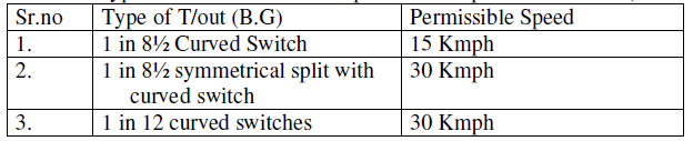
• Turnouts- Speed in excess of 15 Kmph should be permitted on t/outs laid with ST or PRC sleepers only. All t/outs on the running loops shall be laid with curved switches with minimum rail section being 52kg. all rail joints on these t/outs should also be welded to the extent possible.
For different type of curved switches the permissible speed are as under( CS.no 94)

• Track on Running loops:- Speed in excess of 15 Kmph should not be permitted
on running loops laid with wooden sleepers. The minimum track structure on the
running loops should be 90R rails laid as short welded panels M+4 density on PRC, St, CST-9 sleepers and 150mm ballast cushion. Out of 150mm total cushion clean cushion of 75mm at least should be available. Drainage of the area should also be ensured..
• Turn-in-curve:- Speed in excess of 15kmph should not be permitted on turn-incurveslaid with wooden sleepers. Turn-in-curves should be laid with the same
rail sections as on the t/out with PRC, ST or CST-9 sleepers with sleeper spacing
being 65cm c/c (maximum).
Turn-in-curves should confirm to given above especially in respect of curvature of lead curve. Extra shoulder width of ballast of 150 mm should be provided on the outside of such turn-in curves.
Turn-in-curves should confirm to given above especially in respect of curvature of lead curve. Extra shoulder width of ballast of 150 mm should be provided on the outside of such turn-in curves.
The frequency of inspection of turn-in curves should be same as that for mainline
t/outs.
B. The following should be ensured, if CST-9 sleepers are used in running loops or turn-in curves.
• There is no crack or fracture at rail seat in 2 consecutive sleepers.
• There is no excessive wear of lug and rail seat.
• All the fittings keys, cotters and tie bars are fitted properly. Rail is held firmly with sleepers.
• Tie bars should not be broken or damaged by falling brake gear wagon parts etc.
And they should not have excessive corrosion or elongated holes. The corrosion
of tie bars inside the CST-9 plates should be specially checked as this result in
their removal and adjustment becoming difficult.
C. The following should be ensured if ST sleeper are used in T/outs, turn-in
curves or running loops.
• There is no crack or fracture at rail seat in 2 consecutive sleepers.
• There is no excessive wear of lug, MLJ and rail seat.
• All the fittings are effective and rail is held with sleepers properly.
• The sleepers and fittings don’t have excessive corrosion, elongated holes etc


No comments:
Post a Comment
Note: Only a member of this blog may post a comment.